Leak-Free Assemblies: Control the Process Part II
In case you missed it, here’s Part I of our Control the Process series.
A variety of factors can inhibit our ability to create sufficient, uniform pressure that is sustained throughout the duration of plant operation. A proper flange seal process addresses each of these factors.
FLANGE SEAL PROCESS
Step 1: Select the right gasket.
- Width
- Is your gasket the correct width for proper seating? Is it the proper width for operating gasket stress? Gasket width directly affects how much stress the gasket sees for a given bolt load.
- Material
- Does your gasket meet material specifications for your operating conditions? The metallurgy of your gasket is as important as its size. You must select a gasket that can withstand operating temperatures sufficiently to maintain sealing stress.
- Type
- Do you have the right gasket type to account for movement between flanges during operation? Your gasket must maintain integrity and contact during flange movement in operation to seal effectively.
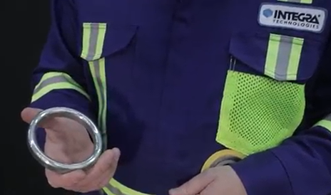
RTJ Gasket
Step 2: Ensure proper gasket Installation.
- Correct gasket
- Selecting the correct gasket for your flange does not ensure that the correct gasket is actually installed. Human error accounts for the vast majority of flange leak sources, including installing the wrong gasket on a flange – even when the correct gasket was available. If you’re experiencing leaks, double check to make sure the correct gasket was installed.
- Centered
- Off-center gaskets are a common source of flange leaks. During assembly, ensure that the gasket is properly centered to avoid leaks.
- Assembled according to design
- Gaskets should not be taped or hung by a string on horizontally running pipes and equipment during flange assembly. Such material can obstruct the seal, providing a path for leaks.
Step 3: Check gasket integrity.
- Surface condition
- Gasket facing assists the gasket in creating an adequate seal for your flange. Facing that has been scratched off will increase the risk of leaks. This can happen more easily than you might think. A gasket that was dropped or stepped on can be damaged, providing a path for leaks to occur.
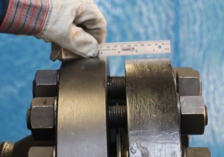
Step 4: Check flange conditions.
- Specifications
- Is your flange facing finish appropriate for your specified gasket?.
- Is your flange flatness within limits? A flange must be sufficiently flat to allow for a uniform seal. Flanges with high and low points beyond specification limits will result in uneven pressure on the flange. Low pressure points will allow fluid to escape.
Flange facing assembly
- Damage
- Is your flange sealing surface damaged beyond acceptable limits? A damaged flange sealing surface is as problematic as a damaged gasket sealing surface. Such damage introduces another path for substances to leak.
- Design
- One source of leaks is a mismatch between the required bolt load and the maximum stress limit of the flange. If the bolt load required to seal the joint during operation exceeds the maximum stress limit of the flange, you will not be able to sufficiently seal the joint without yielding the flange. This error is common in 150# flanges, for example.
- Tight spacing around flanges might prevent the operator from using the correct tooling necessary to achieve proper bolt load. Such situations might require specialty products, tooling, or services to ensure sufficient bolt load is achieved.
- Alignment
- Flanges must be aligned prior to applying full bolt load to properly seal. Attempting to align flanges by applying bolt load (tightening the bolts) can misdirect the potential load toward flange alignment and away from gasket stress, increasing the potential for leaks.
- In these cases, external aligning tools should be used to align the flange instead of using the bolt load to align the flange.
- Flanges must be aligned within industry standards to provide sufficient stress to ensure an adequate seal.
Flange alignment
Step 5: Select the right hardware.
- Hardware specifications
- Ensure that all hardware assembled into the flange meets the specifications for that type of flange. For example, using B7 studs in a high temperature exchanger that requires B16 studs will increase your risk.
- Washers
- Some flanges require washers for torquing.
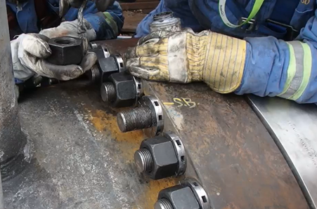
- Nuts and studs
- Ensure proper nut orientation. Nuts that are installed upside down can have a large impact on friction estimation, preventing adequate seal.
- Incorrect, insufficient, or absent lubrication on studs can prevent adequate bolt load application, leading to leaks. This is a very common and pervasive problem seen and corrected by our technicians in the field. Furthermore, studs must be lubricated prior to being assembled into the joint.
Application of correct lubrication on nuts
-
-
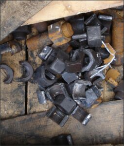
- Friction estimates must be adjusted when reusing old studs and/or nuts to account for the effect of wear and tear. .
-
- Bolts
- Bolt material must be correct for the specified temperature of the application. If your bolt metallurgy cannot accommodate the temperatures reached by your bolted joint in operation, the bolts will relax too much. This will reduce stress on the flange and gasket, creating paths for leaks.
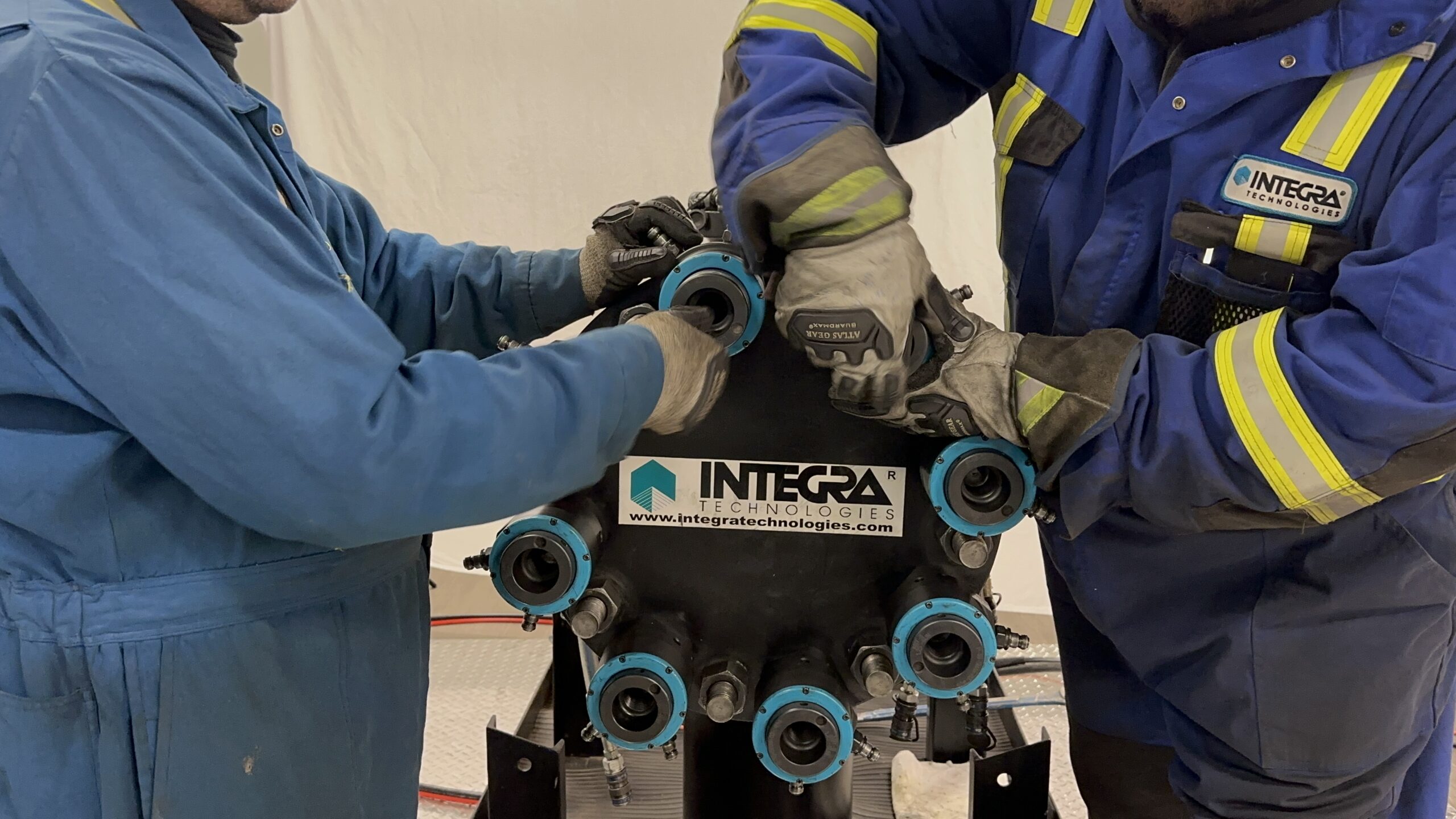
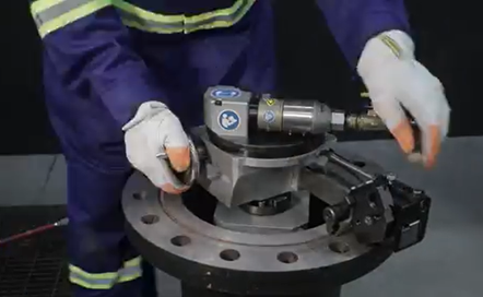
Step 6: Use and maintain the appropriate bolt load.
One of the more common mistakes we see that lead to leaks is insufficient load applied to the bolts. Remember, flanges don’t leak when we don’t give them a path to leak. One of the most important factors for preventing leak paths is to apply more stress to the flange seal through the bolts than the fluid is applying from within the flange. Your bolt load must be high, and it must be uniform, or you will not maintain a leak-free assembly.
LOADING PROCEDURE
- Bolt load
- Utilize the appropriate bolt load specified to seal the flange during operation. We control leaks by applying sufficient and uniform stress to the flange seal. Appropriate bolt load is necessary for this step.
- Verify that the appropriate load was applied to ensure adequate load during operation.
- Galling
- Galling of studs during the torquing.
Galling of studs
- Yielding
- Bolts can be stretched beyond their elasticity, causing permanent plastic deformation of the bolt and decreasing its ability to retain sufficient load on the flange. Bolts that have yielded must be replaced.
- Uneven load on the bolts around the circumference of the flange.
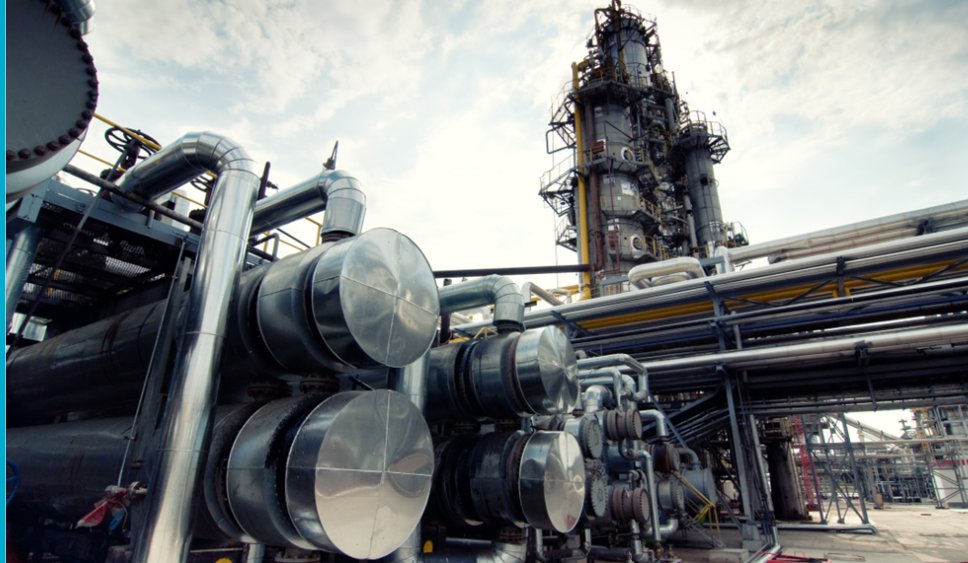
Step 7: Consider temperature.
Temperature is fundamental to the functioning of your bolted joint components. Plants operate at much higher temperatures than the ambient temperature experienced during maintenance and hydrotests. High temperatures tend to cause materials to relax and degrade, allowing more opportunities for leaks to occur. Cyclical temperatures further this issue by producing a relaxation or load loss ratcheting effect on your bolted joint components, decreasing sealing stress and increasing the chance of leaks over time.
Careful consideration of the following factors will help prevent leaks caused by high operating temperatures or cycling temperatures.
- Effect on the gasket
- A large temperature difference between mating flanges can cause radial sheer on the gasket, wearing away gasket facing and producing a path for leaks.
- Effect on bolts
- Relaxation of the bolt material at higher temperatures can reduce bolt stress, weakening the seal and producing a path for leaks. It is possible for a bolt load to be just barely sufficient enough to endure a hydrotest but weaken at operating temperatures, causing a leak during operation despite a successful hydrotest.
Stay tuned for Part III of our Control the Process series.